
Disaster by Design/Safety by Intent #30
Disaster by Design
Defense-in-depth is a primary element of the Nuclear Regulatory Commission’s approach to the safety of U.S. nuclear power plants. Many of the NRC’s regulatory requirements seek to reduce the chances of reactor core meltdowns to as low as achievable levels. But recognizing that the consequences of low probability events like meltdowns, sometimes called “black swans,” can be disastrous, the NRC also has regulatory requirements seeking to reduce the chances that radioactivity gets released in harmful amounts during an accident. This commentary describes the primary containments used in pressurized water reactors (PWRs) and boiling water reactors (BWRs) and how too much pressure can cause containment to fail.
PWR Containments
PWRs comprise about two-thirds of the U.S. nuclear power reactor fleet. These PWRs feature two types of containment design: large dry containments and ice condenser containments.
The typical large dry containment (Fig. 1) has a steel-lined, reinforced concrete structure completely surrounding the reactor vessel (red object), steam generators (blue objects), and reactor coolant pumps (green objects). If a pipe connected to the reactor vessel breaks, the containment handles the energy released with the fluid jetting from the broken pipe ends. Emergency equipment housed in adjacent buildings start up and supply cooling water for the reactor, and also for the containment.
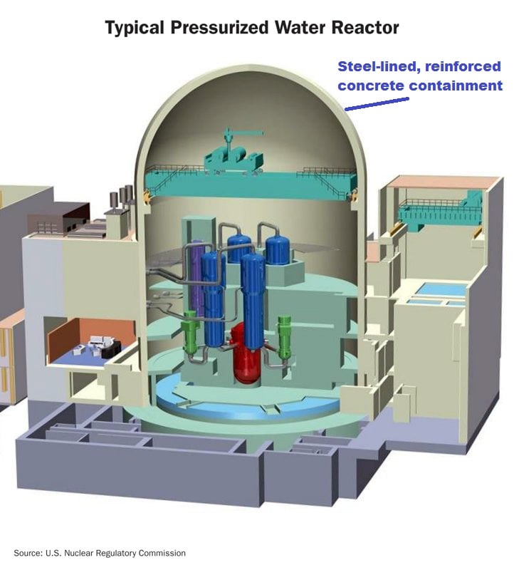
Fig. 1 (Source: NRC)
Fewer than a dozen U.S. PWRs are equipped with ice condenser containments (Fig. 2). Their steel-lined, reinforced concrete structures completely surround the reactor vessel and associated equipment, but also enclose large vaults filled with ice—lots and lots of ice. Should a pipe connected to the reactor vessel break, the fluid discharging into the containment atmosphere will push open doors to the ice vault. The fluid (steam) cools as it flows past the ice and turns back into the water phase. Ice condenser containments are also called pressure suppression containments because the ice functions as an “energy sponge” soaking up energy released into containment during an accident, thereby reducing the pressure inside containment below what it would be otherwise.
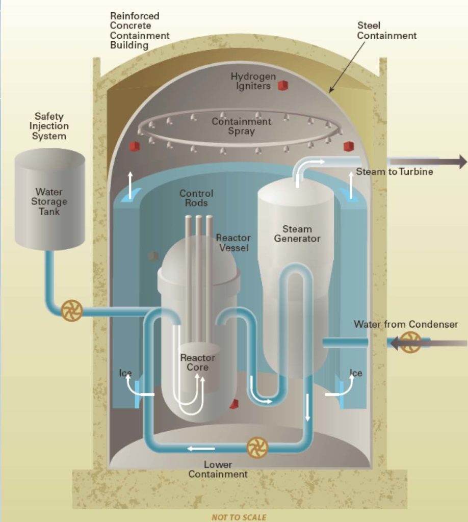
Fig. 2 (Source: Nuclear Regulatory Commission)
BWR Containments
BWRs form about one-third of the U.S. nuclear power reactor fleet. These BWRs feature three containment designs (Fig. 3). All three designs are pressure suppression containments, but they rely on water in its liquid form rather than in ice form as used in the PWR ice condenser containments. The Mark I, Mark II, and Mark III containment designs employ water—lots and lots of water—as the “energy sponge” to soak up energy released into containment during an accident. This water is stored in the suppression chamber (sometimes called the torus in Mark I designs), wetwell, or suppression pool. The drywell is the space enclosed by the reinforced concrete containment structure.
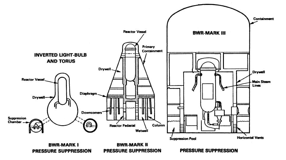
Fig. 3 (Source: Nuclear Regulatory Commission NUREG-0474)
Containment Designs
Two parameters are often used when comparing various nuclear plant containment designs (Fig. 4). The containment net free volume represents the space within the reinforced concrete containment structure minus the space occupied by walls, pumps, pipes, and other components inside containment. The design pressure represents how much internal pressure the reinforced concrete containment structure is designed to withstand.
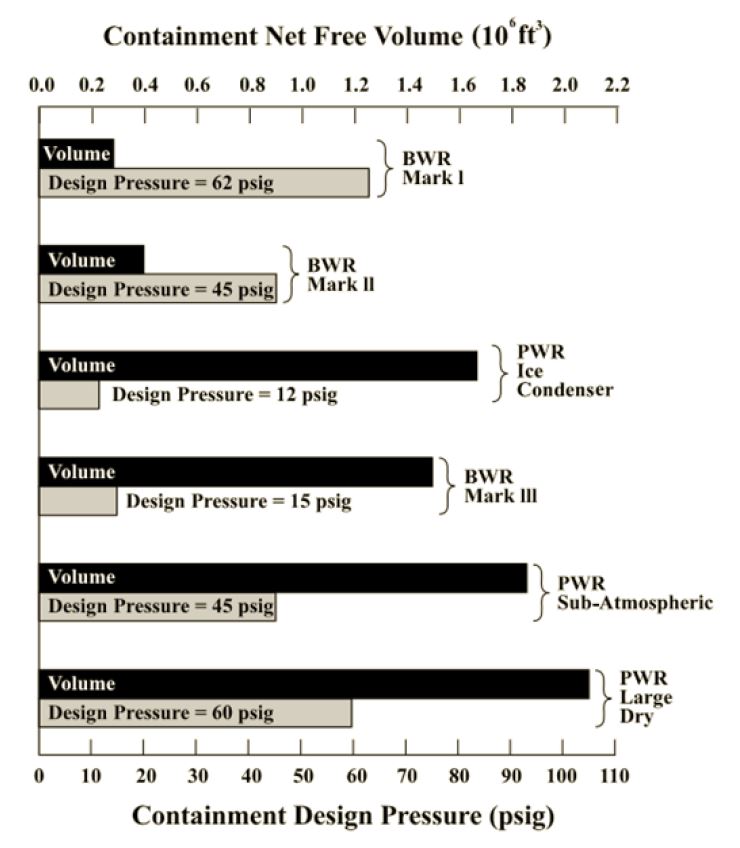
Fig. 4 (Source: Nuclear Regulatory Commission)
The owners submitted results from calculations of peak containment pressure during postulated accidents to the NRC when seeking the original reactor operating licenses. The peak containment pressure had to be less than the containment design pressure; otherwise, the integrity of this vital defense-in-depth barrier could be compromised.
When Good Containments Go Bad
Containment integrity can become compromised (i.e., fail) if the internal pressure during an accident rises above the design pressure. An over-pressurized containment would not burst like a balloon. But the excessive pressure could find a weak link in the containment chain (such as the filling used to seal around a pipe penetrating through the concrete wall) and push it aside to create an opening for pressure, and radioactivity, to escape from containment. There are several ways for the containment pressure to rise above the design pressure to challenge containment integrity.
The Energy Accounting Way
One way for containment pressure to rise above design pressure during an accident involves inaccurate energy accounting during the computer studies.
The owner of the three pressurized water reactors at the Oconee nuclear plant in South Carolina notified the NRC in September 2004 of such an accounting glitch. Among the many safety studies prepared by the owner and reviewed by the NRC en route to the reactor operating licenses being issued was one for the postulated break of a pipe between the steam generator within and the turbine outside containment. Oconee has an Automatic Feedwater Isolation System that is designed to automatically close valves in the pipes supplying makeup water to the steam generators when a steam pipe break is detected. Closing these valves stops the flow of water into the steam generators, which in turn stops the flow of steam out from the broken end of the pipe. Stopping this steam flow limits the amount of steam and energy released into the containment from the broken pipe. The original safety study assumed a shear break (often termed a “guillotine break” because it assumes the quick and complete cut through the pipe from to bottom) of the 34-inch diameter steam pipe.
In 2004, workers at Oconee identified a shortcoming in the original analysis of a steam pipe break. When a smaller break occurred, such as from a few inches of a faulty weld, the smaller amount of steam escaping into containment caused its temperature and pressure to increase at a slower rate. This less severe transient means it takes longer for the Automatic Feedwater Isolation System to detect the break and trigger the automatic closure of the valves in the pipes providing makeup water to the steam generators. These valves are pneumatically controlled. They require compressed air from the Instrument Air System to move. But the Instrument Air System is not a safety-related system and may stop working during an accident and when electricity from the offsite power grid is lost. Workers calculated that the pressure within the Instrument Air System could drop below the pressure needed to close the valves in about two minutes. Thus, if the size of the steam pipe break was not large enough to trigger automatic closure of the makeup valves within two minutes, the valves might not close.
If the valves did not close, the continued flow of makeup water to the steam generator will continue to discharge steam into the containment from the broken pipe end. Workers calculated that the pressure inside containment would eventually increase above the design pressure.
The Spray Way
BWR and PWR containments feature carwash-styled spray nozzles mounted to their upper walls and roofs. Workers can start pumps and open valves to spray cool water into the containment through the nozzles. The water spray reduces the temperature and pressure of the containment atmosphere. If the containment spray function becomes unavailable, either due to loss of power for the pumps or by malfunction, the containment pressure can rise above the design pressure.
Owners have notified the NRC of several reasons why the containment spray function may have failed during an accident. In June 2015, workers at Fort Calhoun (NE) reported the failure of the original design evaluations to account for the thermal stresses from the heatup of the containment spray piping during the early stages of a postulated accident. The energy released into containment during an accident would heat up the pipes to 290°F. The metal pipes would expand as they heated up, imposing stresses above those specified in the piping codes and standards issued by the American Society of Mechanical Engineers. The owner informed the NRC that even though the containment spray piping would have experienced stresses greater than allowed by the codes, the piping probably would have remained intact. Had it failed, the containment spray system would have been unable to reduce the temperature and pressure within the containment.
In July 2014, workers informed the NRC that one of the two containment spray trains at the Millstone Unit 2 reactor in Connecticut was inoperable due to the discovery of air pockets within the system’s piping. The reactor had been shut down for a refueling outage. During the outage, testing and inspection activities allowed some of the water to drain from the containment spray piping and be replaced by air. Workers were supposed to open valves to allow air to vent from the pipes as they were being filled with water. But they failed to do an adequate venting job such that significant amounts of air remained trapped in the piping when the reactor restarted. This air could have prevented this train of the containment spray system from functioning properly during an accident.
Some PWRs and all BWRs rely on pressure suppression to limit peak containment pressure during an accident. These pressure suppression containment use water as an “energy sponge” to soak up energy that would otherwise go towards increasing the temperature and pressure of the containment atmosphere. But pressure suppression fails when the sponge gets saturated and when fluid bypasses the sponge.
Workers informed the NRC in October 2005 that the boiling water reactor at the Hope Creek nuclear plant in New Jersey had to be shut down because one of the torus/drywell vacuum breakers had partially opened and could not be reclosed. Hope Creek has a Mark I pressure suppression containment design. Eight large diameter vent lines connect the drywell part of containment with the wetwell or torus part. During an accident, the steam released into the drywell from a broken pipe flows down the vent lines and emerges below the water line of the torus. This steam flow entrains the nitrogen that inerts that drywell during reactor operation. The steam gets condensed by the torus water; the nitrogen gas bubbles through the water to fill the air space inside the torus above the water line. When the pressure inside the torus rises too much above the pressure inside the drywell, the torus/drywell vacuum breakers automatically open to allow nitrogen gas to flow through the vent lines back into the drywell.
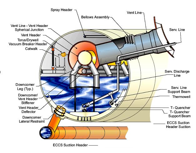
Fig. 5 Cutaway of a Mark I torus (Source: Nuclear Regulatory Commission)
But an open torus/drywell vacuum breaker allows steam to flow into the air space above the torus water line without passing through the water, bypassing the “energy sponge.” Workers had to shut down Hope Creek because the open vacuum breaker could have caused the pressure inside the drywell to exceed its design limit during an accident. Workers discovered that a loose locknut on the valve allowed it to partially open.
More recently, in November 2011, the owner of the boiling water reactor at the Cooper nuclear plant in Nebraska also informed the NRC about an open torus to drywell vacuum breaker. This vacuum breaker did not open due to a loose locknut or other malfunction. Instead, a worker taking a rolling podium for a stroll through the control room managed to hit the handswitch for the valve, turning the handswitch and opening the valve. (The plant’s procedures did not allow the rolling podium to be within four feet of the control room panels, so either the valve’s control switch was unusually long or the procedure was violated.) The opened valve was immediately noticed and manually reclosed. The report to the NRC did not specify whether the rolling podium was once again to whap the handswitch or whether a more traditional method was employed.
Safety by Intent
During a meeting with nuclear industry representatives in June 1986, Harold Denton—then Director of the Office of Nuclear Reactor Regulation at the NRC—infamously stated that the agency’s foremost safety study at that time concluded that there would be “something like a 90% probability that containment” on a boiling water reactor would fail in event of an accident. Since the primary, secondary, and tertiary objectives for bothering to install containments is to protect the public in event of an accident, a 1 in 10 chance of meeting those objectives seems woefully insufficient.
Much has happened since Mr. Denton made that statement nearly thirty years ago. The NRC mandated that owners address pressure buildup in BWR pressure suppression containments, potential impairment of the containment spray function in PWRs during to debris on screens protecting the pumps, accumulation of gas inside containment spray systems in PWRs and BWRs, and many other measures to restore or upgrade safety. Collectively, these efforts have almost certainly improved the reliability of containments as protective barriers in event of an accident.
But, however close that reliability is to 100%, it is not an absolute guarantee. If any single layer of defense-in-depth was perfectly reliable, the other layers would not be needed. Because all of the layers are imperfect, safety is best served by as many layers as practical with each barrier being as reliable as reasonably achievable.
Safety is also well served by avoiding the trap inherent with defense-in-depth’s multiple layers. It can be wicked tempting to rationalize a known impairment in one layer on the basis that other layers will guard against disaster in the unlikely event of an accident. The surest way to avoid this trap is to assume that each layer is the only barrier against disaster. Giving each barrier the respect it deserves rather than spreading it across all the barriers assures known that deficiencies are found and fixed in a timely, effective manner.
Watch out for rolling podiums!
—–
UCS’s Disaster by Design/Safety by Intent series of blog posts is intended to help readers understand how a seemingly unrelated assortment of minor problems can coalesce to cause disaster and how effective defense-in-depth can lessen both the number of pre-existing problems and the chances they team up.