Nuclear Energy Activist Toolkit #63
The original licenses issued by the NRC for nuclear power reactors permit operation for up to 40 years. Owners can, and many have, applied to the NRC for license renewals that permit operation for up to 20 more years.
While calendars are involved, the owners and the NRC use other means to determine nuclear plant lifetimes.
How Do You Tell a Nuclear Plant’s Lifetime?
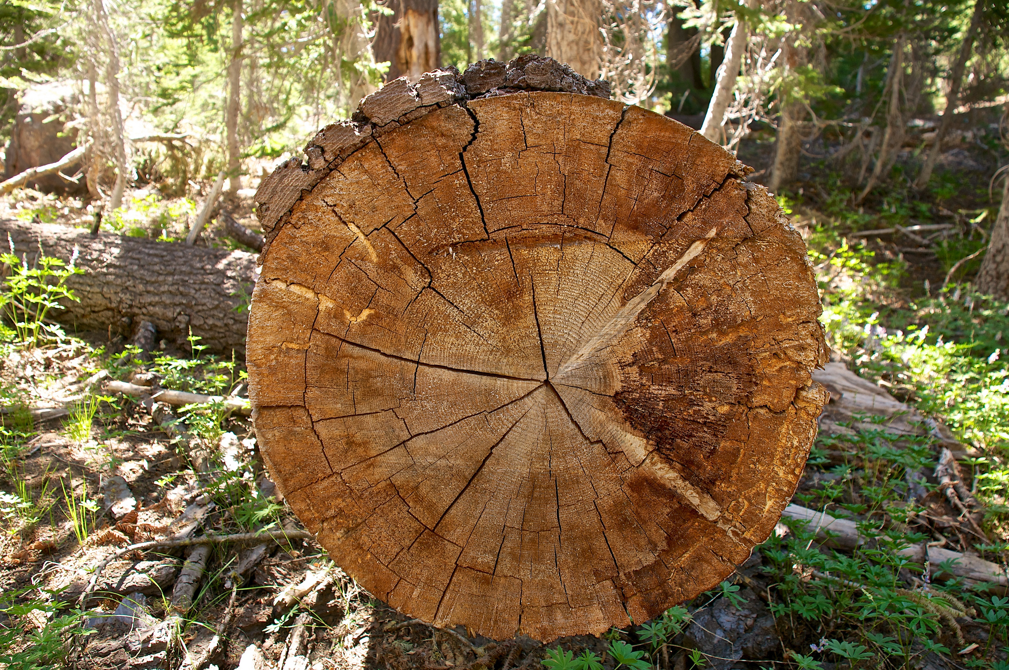
Fig. 1 (Source: Flickr-Tree Rings by Don DeBold)
Sawing it in half and counting the rings may determine the age of a tall woody plant (i.e., tree), but it doesn’t work for nuclear plants tall or small. And even if it did, the process ends the lifetime and provides insights only about the past.

Fig. 2. (Source: Flickr-Abracadabra! by Kenny Louie)
Like doctors treating patients, owners and the NRC don’t saw nuclear plants in half. Instead, they employ an array of techniques to first predict nuclear plant lifetimes and then monitor reactor lifes against the predictions. Two of those techniques are design cycles and cumulative usage factors.
Design Cycles
Long before a nuclear plant is licensed and operated, its owner develops design cycles. As shown in this table (Table 1) from the safety study for a U.S. nuclear power plant now operating, design cycles are the number of operational events the plant might experience over its 40-year lifetime. Item 6, for example, indicates that the plant might experience 400 trips (i.e., shut-downs) of its reactor from full power (FP)—an average of 10 trips per year or roughly one trip per month (considering that the reactor will be shut down some months for refueling and maintenance).
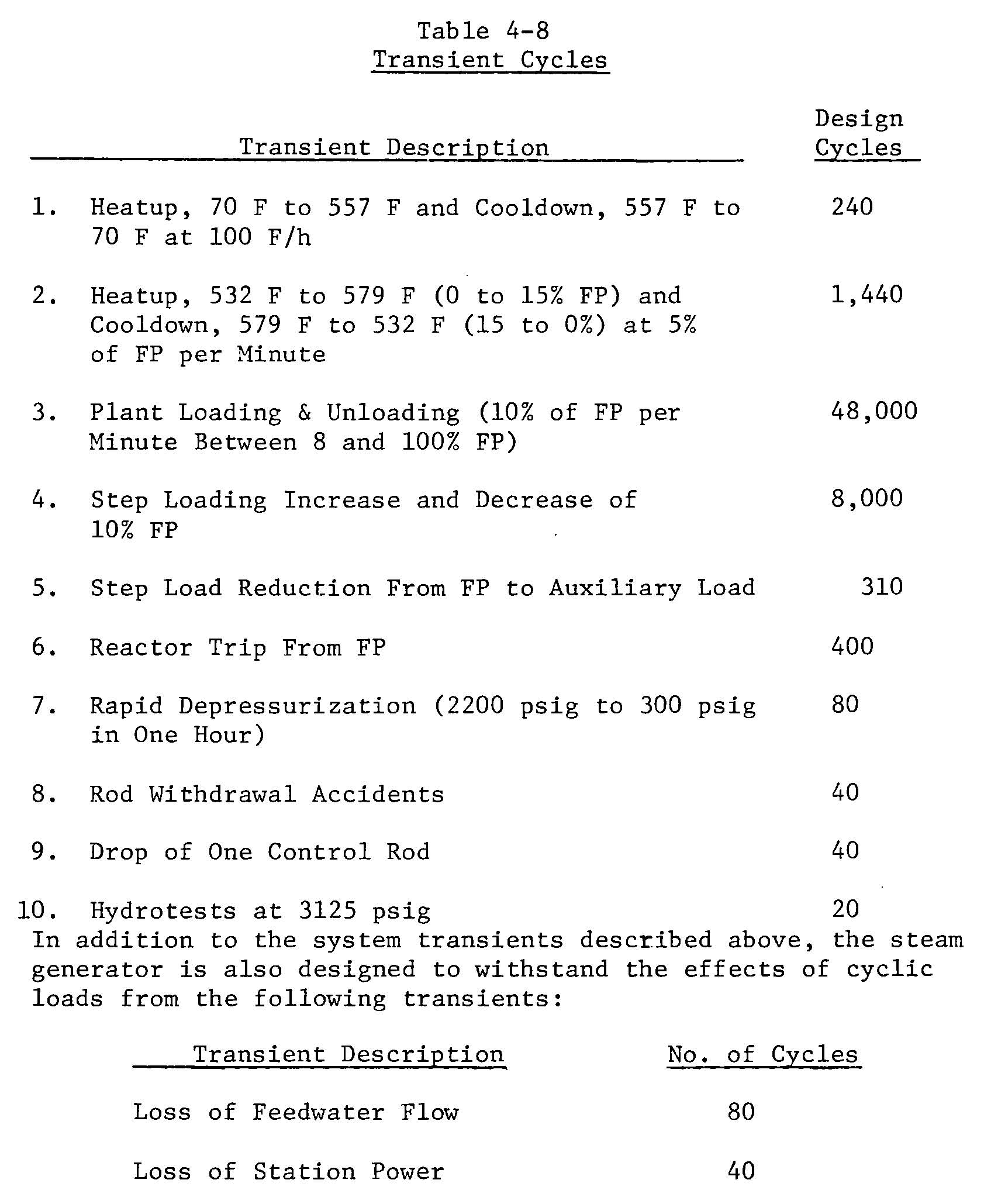
Table 1. (Source: Nuclear Regulatory Commission)
The first item indicates 240 heatup and cooldown cycles. A full heatup cycle goes from the temperature during cold shutdown (70°F) to the temperature at full power (557°F) at a rate of 100°F per hour while a full cooldown cycle is just the opposite.
Several design cycles are specified because the plant is not a single homogeneous hunk of metal. It consists of dozens of systems, thousands of components, and miles of piping. A rod withdrawal accident (item 8) affects different parts of the plant than a loss of station power (the second “bonus” design cycle).
Engineers use the design cycles, along with input about system functional requirements, to determine the types, sizes, and ratings of pipes and other components installed in the plant.
NRC reviewers use the design cycles to determine whether the proposed design of safety systems and components complies with federal regulations.
The design cycles are neither guarantees nor absolute limits. The Unit 2 reactor at Three Mile Island only experienced about 34 reactor trips, and not all of them were from full power. But its final trip was a doozy that ended that unit’s lifetime no matter what the design cycles tally said.
Consider the first item—heatup from 70°F to 557°F at a rate of 100°F per hour. What if the plant was at 80°F when it began the heatup? Would that count as only 97.9% of a cycle since it only included 477°F of the 487°F specified by that design cycle? Or, what about a heatup that went from 70°F to 557°F, but at a rate of only 80°F per hour? Would that slower heatup pace warrant counting it as only 80% of a cycle?
Cumulative Usage Factors pro-rate the design cycle count, but using far more sophisticated, math than suggested above.
Cumulative Usage Factors
Cumulative Usage Factors (CUFs) are more discrete measures of lifetime than design cycles. CUFs also look at lifetime from a different, albeit related, perspective. Design cycles anticipate how many operational events a plant could experience to shape decisions about installing materials that ensure this expected wear and tear. CUFs account for the wear and tear on components within the plant based on its history of actual operational events and a forecast of operational events (i.e., design cycles) over its remaining lifetime.
Table 2 lists CUFs for a U.S. nuclear power plant. CRD stands for the control rod drive system. RHR stands for the residual heat removal system, and RR stands for the reactor recirculation system.
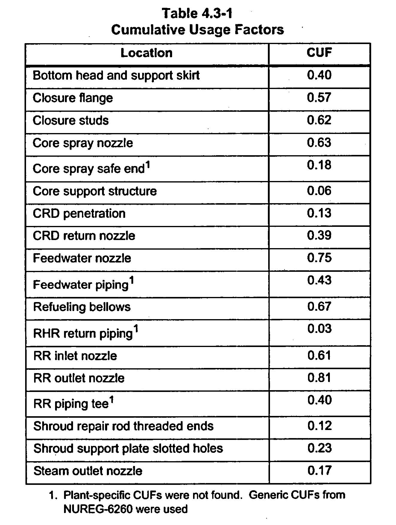
Table 2. (Source: Nuclear Regulatory Commission)
This plant had experienced X design cycles and was anticipated to experience Y more design cycles for a total of Z design cycles. Yet it has CUFs ranging from as low as 0.03 to 0.81. Why the wide range? And what does a CUF number mean?
A CUF of 1.0 means that wear and tear has degraded a component’s material properties (e.g., its strength) to the point where the safety margin is zero. A CUF of 0.0 means that a component’s safety margin is 100% and it as experienced no discernible wear and tear. Values between these endpoints track the lifetime used and indicate the remaining lifetime.
CUFs vary within a nuclear plant because components are made from different materials and are installed in different geometries. Materials expand while being heated up and contract while being cooled down at rates determined by their types. Expansions and contractions can cause stresses within materials that induce cracks and causes cracks to grow larger. Components of the exact same size and shape from the same material experiencing identical heatup or cooldown can experience differing CUFs when one is free to expand and contract while the other is wedged solidly between two hard objects.
Five of the CUF valves from Table 2 above are shown in this cross-section of a reactor vessel (Fig. 3). All five CUFs are for nozzles where pipes are welded to the reactor vessel. The CUFs vary from 0.17 for the main steam nozzle to 0.81 for the recirculation outlet nozzle.

Fig. 3. (Source: Nuclear Regulatory Commission with CUFs Added by UCS)
CUFs for past operational events are determined by calculation. Workers cannot carry a CUF-stick or CUF-ometer out into the plant to measure a nozzle’s CUF valve. The calculations account for each component’s material properties, size, and geometry and temperature, pressure, and radiation conditions at each component’s location during each operational event to determine the individual CUFs.
What Happens When the Number of Design Cycles is Exceeded or a CUF Reaches 1.0?
Design cycles are primarily inputs to the licensing and relicensing processes rather than hard and fast limits. Thus, the number of design cycles can be safely exceeded.
The exception to this rule occurs when CUFs have not been calculated and maintained. The number of design cycles can be exceeded when CUFs show that components still have safety margins remaining. Absent this showing, the number of design cycles defines the safety margins and that boundary cannot be safely crossed.
When a CUF reaches 1.0, that component’s useful lifetime has been used up. CUF context becomes important. CUFs can represent only the accumulated wear and tear from actual operational events to date. Or CUFs can represent the accumulated wear and tear as well as the anticipated wear and tear over the remaining license period for the plant. If it is the latter context, a CUF of 1.0 should spur that owner into planning to replace or repair the component and/or to seek to reduce the number and magnitude of operational events in the future so as to prevent the accumulated wear and tear component from reaching 1.0.
Sometimes, CUFs are recalculated so as to reduce the accumulated wear and tear value from past operational events. The original calculations may have used conservative assumptions about temperature ranges and/or temperature change rates. As CUF valves approach 1.0, recalculations can reduce the CUF by using more accurate data. This process is like someone writing a number of checks while keeping a ballpark tally in his or her head of how they are dropping the account’s balance, but then going online to confirm the actual balance or using a calculator to cipher the more precise remaining funds before writing the next checks.
Bottom Line
Design cycles and cumulative usage factors are guides, not guarantees. Three Mile Island Unit 2 was licensed for 40 years and expected to experience hundreds of reactor trips over that 40-year operating lifetime. Its lifetime expired after only about one year and 34 reactor trips.
Design cycles and cumulative usage factors are but two of many indicators of available safety margins. Periodic inspections, such as x-raying welds and ultrasonically measure pipe wall thicknesses, also check whether safety margins are adequate.
No single method is 100 percent reliable. If one was that reliable, the other methods would not be used.
All the methods combined are not 100 percent reliable. If collectively they were that reliable, then containments and emergency planning and federal liability insurance protection would not be required.
Defense-in-depth works best when each barrier is as reliable as possible and as independent form other barriers as possible.
The CUFs on the reactor vessel above illustrate a tempting trap that must be avoided. The CUFs for the recirculation, feedwater, and core spray nozzles are at least three times higher than the CUF for the main steam nozzle. It would be tempting to use this data to cut back inspections of the main steam nozzle and reallocate those inspection resources to additional examinations of the recirculation outlet nozzle.
But doing so, however tempting, defeats defense-in-depth for the main steam nozzle. The inspections backstop the CUF calculations. If the CUF calculation is wrong or if some other factor (such as a pre-existing weld defect), not doing the inspections removes this safety net and makes a bad outcome easier to reach.
The UCS Nuclear Energy Activist Toolkit (NEAT) is a series of post intended to help citizens understand nuclear technology and the Nuclear Regulatory Commission’s processes for overseeing nuclear plant safety.