
Nuclear Energy Activist Toolkit #43
The primary objective of nuclear power plants is to generate electricity for use (i.e., purchase) by industrial and residential customers. Nuclear power plants consume large amounts of electricity themselves in pursuing this objective.
Electrical distribution system drawings, sometimes called single-line drawings, illustrate the major circuits used to supply electricity to the offsite power grid and to supply electricity to plant equipment. Figure 1 shows the normal and standby (or emergency) electrical distribution system for the Browns Ferry nuclear plant in Alabama. The concept applies similarly to all nuclear plants in the United States.
Brown Ferry’s Electrical System
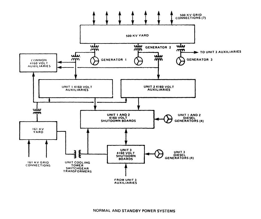
Fig. 1: (click to enlarge) (Source: NRC)
The electrical switchyard—the primary connection between the plant and its offsite power grid—appears at the top of Figure 1. In this case, it’s a 500 kilovolt (kv) switchyard, meaning that each transmission line radiating from the plant carries 500,000 volts of electricity. Seven 500,000 volt transmission lines connect this plant with its offsite power grid. Federal regulations, specifically General Design Criterion 17 of Appendix A to 10 CFR Part 50, require at least two connections that are as unlikely to fail for the same cause as possible. While extreme weather, like a tornado or hurricane, might disable all the transmission lines, the regulation seeks to prevent a single lightning strike or transmission tower collapse from disconnecting the plant from the offsite power grid.
Generators and Transformers
The three reactors at Browns Ferry each have a main generator that can supply electricity to the 500,000 volt switchyard. These generators are shown by the Circle-Y symbols just below the 500 kv switchyard. The opposing mini-caterpillars or extended-m’s between the generators and the 500 kv switchyard represent electrical transformers. Electrical transformers are used to increase or decrease the voltage level of electricity. When the unit is operating at power, the 22,000 to 24,000 volt current produced by the main generator is increased to 500,000 volts for transmission from the switchyard. Some of the generator’s output flows to another transformer where its voltage is decreased to 4,160 volts for use within the plant.
When a unit is shut down, electricity from the 500,000 volt switchyard flows to the transformer that reduces the voltage to between 22,000 and 24,000 volts. An opened electrical breaker (not shown in the drawing but essentially a switch connecting or disconnecting the power line from the generator to the switchyard) prevents the electricity from reaching the generator. Electricity flows through a second transformer where its voltage gets reduced to 4,160 volts.
Auxiliary and Shutdown Boards
At Browns Ferry, electricity from the switchyard or from the main generator is supplied to the Unit Auxiliary and Shutdown Boards. These boards are the nuclear plant equivalent of main power panels in houses. In homes, the panels receive electricity from the local power grid and provide it via breakers (or fuses in older configurations) to electrical circuits throughout the house. Similarly, breaker-controlled cables connect the Unit Auxiliary and Shutdown Boards to equipment throughout the plant. An open breaker de-energizes the cable. A closed breaker sends electricity through the cable to equipment. Equipment connected to an energized cable may have a separate on/off switch to control its operation.
The Unit Auxiliary Boards, such as the one pictured in Figure 2, supply electricity to non-safety-related components like the lubricating oil pumps for the main turbine and the lights in the turbine building. The compartments across the bottom and on the right house electrical breakers. The instruments and switches on the left of the board monitor and control the power supply to the board.

Fig. 2: Unit Auxiliary Boards (Source: TVA)
The Unit Shutdown Boards power safety-related components like the emergency coolant pumps and the containment cooling systems.
General Design Criterion 17 requires redundancy in offsite transmission lines and in the internal plant electrical distribution, too. The Unit 1 and 2 reactors at Browns Ferry are each equipped with two emergency diesel generators that can supply electricity to the Unit Shutdown Boards. The Unit 3 reactor has four emergency diesel generators. If even one diesel generator per reactor functions, sufficient power is provided through the Shutdown Board for the equipment needed to mitigate an accident.
Browns Ferry has a second switchyard, shown in the lower left corner of the drawing. This switchyard connects the plant to two 161,000 volt transmission lines. While these lines cannot be used to transport electricity generated by the plant, they may supply electricity from the 161,000 volt offsite power grid to plant equipment. Two separate transformers can reduce the voltage down to 4,160 volts to supply the Unit Auxiliary and/or Unit Shutdown Boards.
There’s diversity and redundancy in the electrical distribution system. The Unit Auxiliary Boards can be supplied from the main generator, the 500,000 volt switchyard, or the 161,000 volt switchyard. The Unit Shutdown Boards can be supplied from these sources or from the emergency diesel generators.
Pilgrim’s Electrical System
Figure 3 is a somewhat less simplified drawing of the electrical distribution system for the Pilgrim nuclear plant in Massachusetts. Pilgrim has a 345,000 volt switchyard, shown in the upper left, with transmission lines to Bridgewater and Canal Station.

Fig. 3: Electric diagram of Pilgrim (click to enlarge) (Source: NRC)
There’s also a separate connection via a 23,000 volt transmission line to Manomet. This 23,000 volt incoming line flows through Shutdown Auxiliary Transformer X13 where its voltage is reduced to 4,000 volts to supply electrical board A8. This offsite source alone could not be used to shut up the Pilgrim reactor because non-safety-related equipment would not be supplied with electricity. But this offsite power source alone could supply power to essential safety-related equipment connected to 4,000 volt electrical boards A5 and A6.
With the plant operating at power, electricity produced at 24,000 volts by the main generator flows through transformer X1 where its voltage is increased to 345,000 volts for the offsite transmission lines. Electricity from the main generator also flows through Unit Auxiliary Transformer X3 where its voltage is reduced to 4,000 volts to feed six electrical boards. Electrical breakers are represented on the drawing as eyeless smiley faces. Breakers that are normally open when the plant is operating at power have “NO” next to the eyeless smiley face. Otherwise, the electrical breakers are normally closed.
When the plant is shut down or the main generator is offline, electricity flows from the 345,000 volt switchyard through Startup Auxiliary Transformer X4 where its voltage is reduced to 4,000 volts to feed six electrical boards. In this situation, the normally opened breakers in the drawing would be closed and the normally closed breakers from the Unit Auxiliary Transformer source would be opened.
Pilgrim has four 4,000 volt non-safety-related electrical boards (A1, A2, A3, and A4) and two 4,000 volt safety-related electrical boards (A5 and A6). These latter two can be supplied from the emergency diesel generators (DG #1 and DG #2).
Each 4,000 volt electrical board provides electricity through transformers that reduce its voltage level to feed 480 volt boards (B1, B2, B3, B4, B6, B7, and B8). Browns Ferry also had lower voltage boards, but they were omitted from its more simplified drawing. Large motors, such as those for the two recirculation pumps, receive electricity at 4,160 volts. The majority of motors in the plant receive lower voltage electricity.
Pilgrim has a Blackout Diesel Generator capable of supplying electricity to 4,000 volt board A8. In the event that electricity from the main generator, the 345,000 volt switchyard, the 23,000 volt switchyard, and Diesel Generator #1 or Diesel Generator #2 is unavailable, the Blackout Diesel Generator can be connected to 4,000 volt board A5 or A6. These safety-related boards can supply 480 Boards B1, B2, and B6 to power their connected components.
There are also drawings for lower voltage power supplies, such as the 125 volt direct current and 24 volt alternating current instrumentation and control circuits. These electrical distribution circuits mirror the convention of redundancy and diversity illustrated in the higher voltage configuration.
Bottom Line
Doctors have a song to help them remember how the bones of the human body are connected. Even if an electrical distribution system song existed, or one bothered to write one, it would have limited use to nuclear plant workers. Unlike the human skeleton, the electrical distribution system connections can be changed to seemingly infinite configurations.
For example, the breaker for the normal power supply from Unit Auxiliary Transformer X3 to 4,000 volt Board A1 is circled in red in Figure 4. The operators could open this breaker and close the breaker circled in green to power this board instead from Startup Auxiliary Transformer X4. Similarly, the operators could manipulate breakers to supply 480 volt Board B2 from its alternate source.
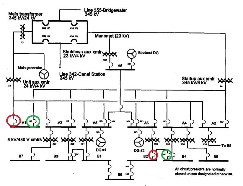
Fig. 4: (click to enlarge) (Source: NRC with UCS annotations)
This flexibility allows portions of the electrical distribution system to be de-energized for testing and maintenance without interrupting the power supply to components at the far ends of the cables. It also makes the electrical distribution system more tolerant of a failure of a breaker or power supply—many of the swap-overs to backup power sources occur automatically when the primary source becomes unavailable. It also provides workers with several options for restoring power to components and circuits when responding to problems.
Flexibility comes at a price. It is challenging for workers to maintain situational awareness when so many different situations are possible. The response to dropping a 600-ton load at the Arkansas Nuclear One nuclear plant on March 31, 2013, was complicated by an atypical configuration of the electrical distribution system. The dropped load ruptured pipes. Water pouring from the broken pipe ends shorted out electrical relays and cables, disabling additional components. Workers quickly de-energized the normal power supplies for the pumps sending water through the pipes. But these components had been switched to an alternate source. It took workers additional time to stop the flooding and the damage it was causing.
The UCS Nuclear Energy Activist Toolkit (NEAT) is a series of post intended to help citizens understand nuclear technology and the Nuclear Regulatory Commission’s processes for overseeing nuclear plant safety.