
Nuclear Energy Activist Toolkit #42
Whenever possible, I like to accompany commentaries about nuclear plant issues with simplified drawings of the systems involved. For example, simplified drawings were featured in a NEAT post about the reactor core isolation cooling system and a Fission Stories post about a problem at Oyster Creek. I’ve been taking it for granted that readers would find these drawings a helpful complement to the text. In hindsight, a better foundation would provide a more meaningful connection between text and drawings. This post is the first in a series of posts seeking to provide a belated foundation for using simplified drawings.
Simplified drawings are less-detailed versions of nuclear plant blueprints. These blueprints—non-simplified drawings—are often classified by the engineering discipline (e.g., mechanical, electrical, civil, instrumentation and control) that creates them. Mechanical drawings include piping and instrumentation drawings (P&IDs) showing the layout of mechanical components such as pipes, valves, pumps, heat exchangers, flow measurement devices, temperature detectors, and pressure gauges. P&IDs is the focus of this post. Future posts will describe other types of drawings.
P&IDs
Figure 1 is the P&ID for the reactor coolant system at the Indian Point Unit 3 reactor. It shows the reactor vessel in the center, the four steam generators, the four reactor coolant pumps, and the piping connecting all these components together. It shows far more—connection points where the chemical and volume control system (CVCS) charging lines tie in, temperature wells (TW) and associated temperature elements (TE), pressure indicators (PI) and associated pressure transmitters (PT), flow transmitters (FT), drain lines with their manual isolation valves, and much more.

Fig. 1 (click to enlarge)
Figure 2 shows the simplified P&ID for the reactor coolant system of a pressurized water reactor like Indian Point Unit 3. It shows the major components and how there are connected, but omits smaller components. In fact, it even omits three of four reactor coolant system loops. One loop showing the steam generator and reactor coolant pump represents the three other essentially identical loops.
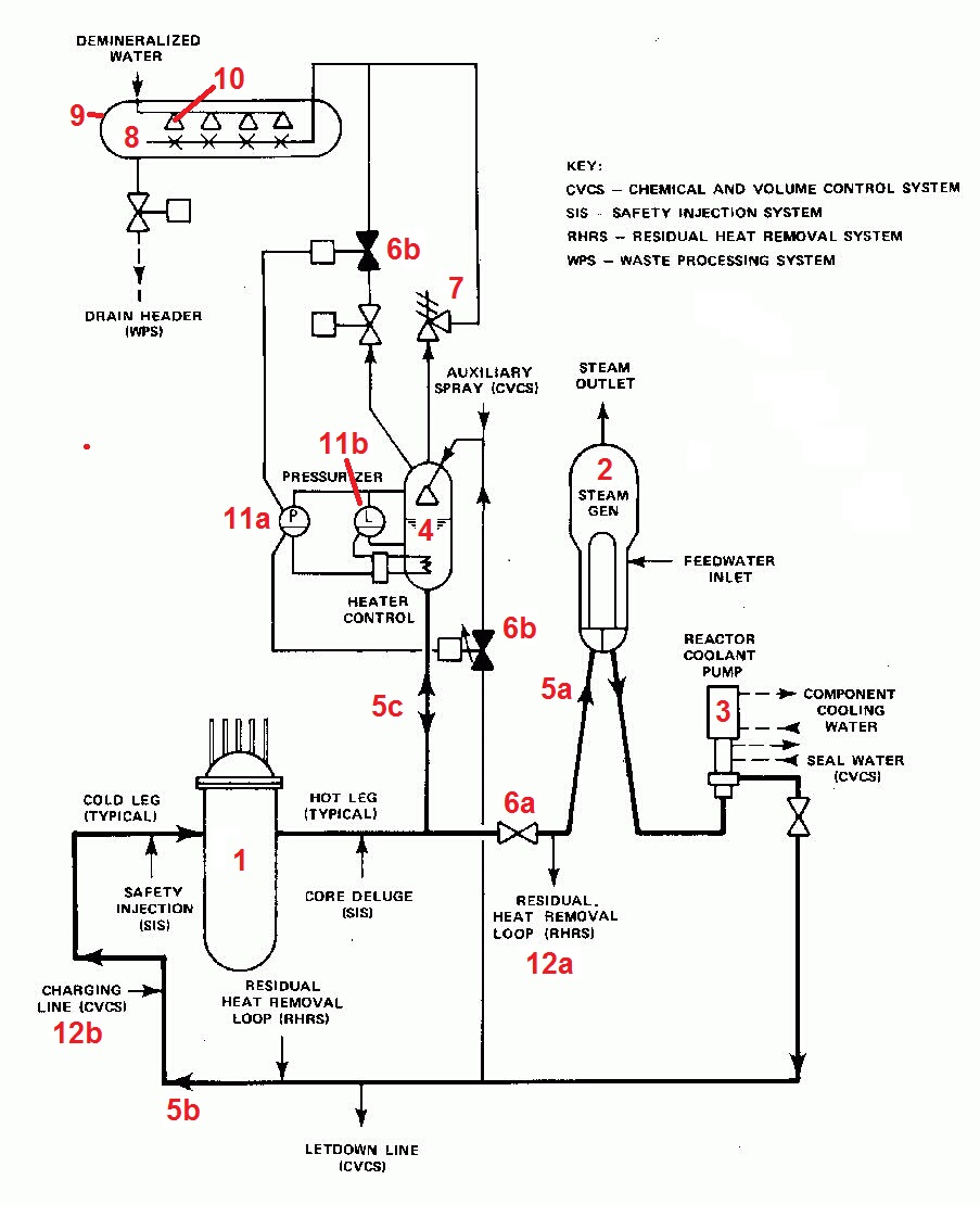
Fig. 2 (Source: NRC) (click to enlarge)
Elements of this simplified P&ID include:
1) The pill-shaped reactor vessel is shown. Additional detail shows the domed reactor vessel head that is bolted on to the top of the reactor vessel. Also shown are the vertical control rod drive mechanisms that penetrate the reactor vessel head to connect the control rods within the reactor core to their motors mounted above the reactor vessel head.
2) One of the lightbulb-shaped steam generators is shown. Additional detail shows that water from the reactor vessel passes through U-shaped tubes inside the steam generator while water from the feedwater system enters the steam generators outside the U-shaped tubes while steam leaves the steam generator. The vertical divider plate is shown in the lower dome of the steam generator to prevent the cooler water exiting the U-tubes from taking a short cut and re-entering a U-tube without first revisiting the reactor vessel.
3) One of the reactor coolant pumps that push water leaving the steam generator back to the reactor vessel is shown. The drawing convention indicates that the reactor pump consists of an electrical motor (the rectangle on top) connected to a pump (the inverted T-shaped lower part). Also shown are the component cooling water system connections that cool the motor and the chemical and volume control system (CVCS) connections that supply sealing water to the pump.
4) The pressurizer is shown connected to the hot leg piping. Additional detail shows that the interior of the pressurizer can be sprayed using water either coming from the cold leg piping or from the auxiliary spray function of the CVCS. Also shown are the wriggly-shaped immersion heater and associated heater control circuit for the pressurizer.
5) The piping appears as either vertical, horizontal, or angled lines connecting the components. Arrows are sometimes applied to show the direction of flow through the pipes. For example, an arrow (5a) indicates that water flows though the hot leg pipe from the reactor vessel to the steam generators. Another arrow (5b) indicates that water flows through the cold leg pipe from the reactor coolant pump to the reactor vessel. And a pair of arrows (5c) indicates that water flows in both directions between the hot leg pipe and the pressurizer. (Not at the same time—the water flows through the pipe into the pressurizer during reactor startups as the water expands during heatup. The water flows through the pipe from the pressurizer after the reactor shuts down and the reactor coolant system’s water shrinks as it cools down.
6) Valves appear as bow-ties on the pipes. White bow-ties (6a) indicate valves that are normally open during reactor operation. Black bow-ties (6b) indicate valves that are normally closed during reactor operation.
7) Another type of valve called a relief valve looks like a broken bow-tie (7). As its name implies, this relief valve automatically opens when pressure inside the pressurizer rises too high. The opened valve “relieves” the high pressure condition by discharging flow in the form of steam or water through spargers (8) into the pressurizer relief tank (9).
8) Spargers (8) are holes or nozzles in a pipe that allow flow from the pipe to be discharged more diffusely.
9) The pressurizer relief tank (9) collects the fluid discharged from the pressurizer (4).
10) Nozzles (10) are triangular shapes (I’d label them half bow-ties, but I’m not sure if they are the bow or the tie half) inside the pressurizer relief tank (9). There’s also a nozzles inside the pressurizer (4). These nozzles are like shower heads—they break up a stream of water into many droplets.
11) The pressurizer is equipped with instruments to measure its pressure (11a) and its water level (11b). Additional detail shows that the pressure instrument (11a) opens normally-closed valves (6b) was necessary to control the pressure inside the pressurizer. If the pressure rises too high, relatively cool water from the cold leg piping can be sprayed into the pressurizer or fluid from the pressurizer can be discharged into the pressurizer relief tank (9). Also shown is the interlock provided from the water level instrument (11b) to prevent the heater from turning on when the water level drops low enough to partially or fully uncover its coils.
12) Lastly, this simplified drawing of the reactor coolant system shows interfaces it has with other major systems. One interface allows water to flow from the hot leg to the residual heat removal system (12a). Another interface allows water from the CVCS charging line to flow into the cold leg (12b) and then into the reactor vessel.
Bottom Line
This simplified P&ID still shows a considerable amount of information, although not nearly as much information as appears on a non-simplified P&ID. Simplified P&IDs are essentially CliffsNotes versions of the non-simplified P&IDs.
One common trap is assuming something does not exist just because it does not appear on a simplified P&ID. Its exclusion might have been one of the many simplifications en route to the CliffsNotes version.
The UCS Nuclear Energy Activist Toolkit (NEAT) is a series of post intended to help citizens understand nuclear technology and the Nuclear Regulatory Commission’s processes for overseeing nuclear plant safety.
Source for Fig. 1: Source: NRC ADAMS